So it seems I failed to give a huge payoff to productivity when using these filters and overrides... VIEW TEMPLATES ...
If you followed the instructions on creating Filters, Fire Ratings & Graphic Overrides then you may have been horrified when you attempted to place these overrides on your other (insert number here) views that need the exact same look...
Well you'd only be horrified if you didn't think of (or remember, or know) that we can use View Templates to propagate these filters & overrides to multiple views... We can!!!
Just Right-Click the view that has the filters and graphic overrides already applied (in the Project Browser) then select Create View Template From View... Once created you can select any & every view necessary and again Right-Click them and this time choose Apply View Template... sit back and let Revit do just that!!! (Insert superlative here)
I love when Revit works for me!!!
Wednesday, October 31, 2007
Wednesday, October 24, 2007
Filters, Fire Ratings & Graphic Overrides
So you want to be a Rock n Roll Star?... Uhh wait... Oh yeah, you want to create fire rated walls in Revit and have them represent visually.... There are many options (OK, a few): One is to use a 'coarse scale fill pattern' and use a hatch pattern (that we usually have laying around from WhateverCAD). This is workable if: 1) You only need them to represent in Coarse views and 2) You only use straight walls, no curves. Not a complete solution and not my choice of them.
My choice is once again to Use Revit Like Revit; thus we will leverage Filters and Graphic Overrides to get this job done to some duplicated Object Types (or do you have them created already?) ...Hmmm...Maybe these should be built into my Project Templates, as well...
In either case we endeavor to Graphically represent our Walls' Fire Rating.
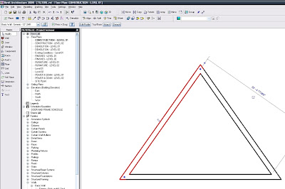
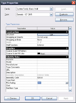
The Wall Type change in action!!! Not so hard, just rename the Duplicate Type and then make the actual addition to the Fire Rating Parameter Value…Yes, I did this for the 1HR wall too...

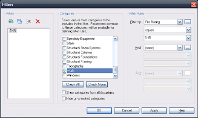
Next, click the “New” button... it's the one that looks like a “green + over paper” symbol…to make your new filters...
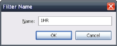
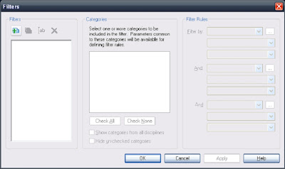 Naming them appropriately for the job they are about to accomplish is of paramount importance.
Then equally (yes, a bit of a pun intended) important is making these filters actually filter the correct parameters and that they ‘equal’ (payoff) the correct value you are to ultimately input in the object’s properties (or in our case the values we already put in our Wall Types). FYI: I also assigned these filters to the “Doors” category…and so can you.
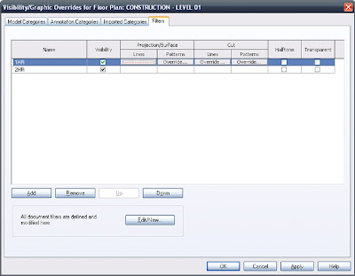
After completing the Filter Creation we can apply them to the view and give the actual Graphic Overrides to the distinctly rated walls...Yes, these filter applications are view-specific!!! So don’t forget to apply them to all the other necessary views you may have...
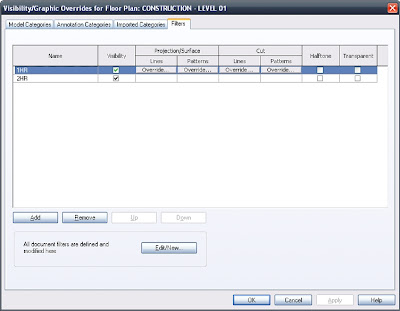
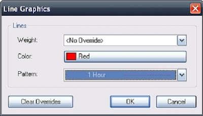
The next two images below are showing the fundamental Overrides that will give the rated walls their look(s)…I know you won’t forget to override both Projection Lines AND Cut Lines…right??? Right!!!
It always helps to have these line styles predefined so they’re available!!! Perhaps 1HR, 2HR, 3HR, 4HR?
And then...
 Ta-Da!!!
Oh and If you didn't realize it yet, you can put a Cut Pattern override as well, so if you have some old (or new) hatch patterns you can use them here as well, just keep in mind that if they consist of thousands of tiny lines there may be a dramatic productivity hit...Kind of "Not-Revit like" if that's the case; but you be the judge...as always.
-J
My choice is once again to Use Revit Like Revit; thus we will leverage Filters and Graphic Overrides to get this job done to some duplicated Object Types (or do you have them created already?) ...Hmmm...Maybe these should be built into my Project Templates, as well...
In either case we endeavor to Graphically represent our Walls' Fire Rating.
Make any (and every?) distinct Wall Type, for each Fire Rating condition you have (at least at this time): Apply or change your walls to those types, as needed in the project (obviously).

The Wall Type change in action!!! Not so hard, just rename the Duplicate Type and then make the actual addition to the Fire Rating Parameter Value…Yes, I did this for the 1HR wall too...

Now here’s the fun part: type VG (or if you’re me VV…no, this isn’t a W, it’s two V’s)… Click over to the Filters tab and then (gently) hit the “Edit/New” button... As it says “All document filters are defined and modified here”.

Next, click the “New” button... it's the one that looks like a “green + over paper” symbol…to make your new filters...
 Naming them appropriately for the job they are about to accomplish is of paramount importance.
Then equally (yes, a bit of a pun intended) important is making these filters actually filter the correct parameters and that they ‘equal’ (payoff) the correct value you are to ultimately input in the object’s properties (or in our case the values we already put in our Wall Types). FYI: I also assigned these filters to the “Doors” category…and so can you.

After completing the Filter Creation we can apply them to the view and give the actual Graphic Overrides to the distinctly rated walls...Yes, these filter applications are view-specific!!! So don’t forget to apply them to all the other necessary views you may have...

The next two images below are showing the fundamental Overrides that will give the rated walls their look(s)…I know you won’t forget to override both Projection Lines AND Cut Lines…right??? Right!!!

It always helps to have these line styles predefined so they’re available!!! Perhaps 1HR, 2HR, 3HR, 4HR?

And then...
 Ta-Da!!!
Oh and If you didn't realize it yet, you can put a Cut Pattern override as well, so if you have some old (or new) hatch patterns you can use them here as well, just keep in mind that if they consist of thousands of tiny lines there may be a dramatic productivity hit...Kind of "Not-Revit like" if that's the case; but you be the judge...as always.
-J
Saturday, October 13, 2007
Slanted Volumes...I guess the Ramp tool isn't enough?
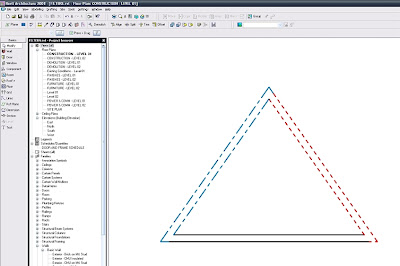
 I've been asked several times in the past few months to create (or show others how to create) Parametric Slanted Volumes. It seems that each time the people wanted to input & Constrain using different values: Well, here are 3 variations of such volumes, including the formulas necessary for their manipulation...(Also included in #'s 2 & 3 are a numerical Parameter that gives the Percentage of the Slope).
1: Control Parameters: Rise & Slope; Run is derived from them.
2: Control Parameters: Rise & Run; Slope is derived from them.
3: Control Parameters: Slope & Run; Rise is derived from them.
Nice!!!
First off use my Revitism: Think Twice and Place Once here...Do these parameters want to be Instance or Type? It's extremely important to choose wisely as changes to the parameters later on may create headaches...(if you use shared parameters, needing to change them later most assuredly will create nightmares (for real))
For these families I used Family Parameters (similar to the image below), all set to Instance and grouped under Dimension...

First, as with all Family Creation I made Reference Planes, Parameterized them, Flexed them at every new parameter and when they were all verified (and only then) did I create the solid geometry; locked to the Ref Planes.
So here are the parameters that are the basis for all three families: Rise, Run, Slope & Width.

Now that I've flexed and see that they work correctly I'll create a solid extrusion. I find it best to lock the extrusion Sketch Lines to the Ref Planes in this sketch mode; just be sure not to 'mix-and-match' lock locations if you lock the sketch lines lock all of them in this mode, don't lock some sketch lines here and other parts of the solid when back in the family editor, in relation to the profile in this case, as you'll probably break the family...

Be sure to use the Align tool and lock the solid to both Ref Planes, that are expressing the Width of the family... (This is OK here and does not constitute a mixing-and-matching of constraints)
 OK!!! So now the foundation is set and we're off to the races.
By using the Family Types tool set the parameters as such:
1) When Rise & Slope are the controlling Parameters, meant to drive the object use the formula: Run=Rise/tan(Slope)...remember to be case sensitive!!!

Here's a flex to test Rise & Slope...
 FILE>SAVEAS>whatever name you like.rfa
Do another immediate SaveAs and rename appropriately for the Rise & Run variation...
Then:
2) When Rise & Run are the controlling Parameters, meant to drive the object use the formula: Slope=atan(Rise/Run).
Here is where I added the Parameter Slope Percentage, as a Number, Instance, Family Parameter...That formula is: Slope Percentage=100*tan(Slope)

A flexing of Rise & Run, to ensure wholesome goodness. -Buttering the bread, as it were...

FILE>SAVEAS>whatever other name you like.rfa
3) When Slope & Run are the controlling Parameters, meant to drive the object use the formula: Rise=Run*sin(Slope).
The Parameter Slope Percentage remains as is: Slope Percentage=100*tan(Slope)

Here's a flex to test Slope & Run... Got sandwich meat? hee hee he said meat...(Props to Beavis...or was that butthead?)
 If you'd like to know what all the expressions are that Revit finds acceptable for use in Formulas go to that button...oh what was that called....umm....ohh....oh yeah: HELP...there is a great list there...
So all is good now in the Basic slanted object world (when the Ramp tool doesn't want to be used)...Now to throw a wrench into your worlds: Why not create a Railing (and all necessary Profiles) and use that for your Conveyor System???
Que Evil Laugh!!!
Mmmmmwwwwwwaaaaaahhhhhhaaaaaahhhhhhaaaaaa........
Wednesday, October 03, 2007
Think twice and place once: Section Marker Control and other Revitisms
So here's the down-low on Section Markers turning off at certain scales; along with a Revitism that's useful for most everything: "Think twice and place once"
Ooooh, I like that -even though it is bastardized from "measure twice and cut once"
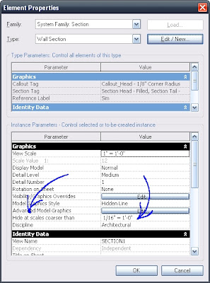
Anyways: The 'on and off-ed-ness' of these Section markers is controlled by the Hide at Scales Coarser Than property.
And:
The Hide at Scales Coarser Than property defaults to the scale value of the view where you placed the section. Right??? Right!!! And if used mindfully can really make this functionality unbeatable!!! That's where the "Think twice and place once" comes into play. (as with most things in Revit!!!)
 If you want the section marker to be visible in views with scales 1/8"=1'-0" and larger (1/4"=1'-0", etc.) then place the sections in a 1/8"=1'-0" view and they (the section markers) will show in views of all scales down to 1/8"=1'-0" but not smaller (or "coarser than" 1/8"=1'-0"; such as 1/16"=1'-0", etc.).
As I said before, the scale of the view where the Section is placed becomes the default value to be found next to Hide at Scales Coarser Than in the properties (see above image), for each section marker... So when working on a project try to (do) keep this in mind since these are instance parameters... so placing a shit-load of sections with an undesired Hide at Scales Coarser Than value can make extra work for...ummm...you???...or those interns (if we can force (i mean convince...I mean ask) them to fix this for us).
Hey J, Can we have Building Sections turn off below 1/8"=1'-0" and Wall Sections turn off below 1/4"=1'-0" just by changing views, or better yet, just by changing the scale of the view we're in?
Yes!!! Oh, and does this apply to Elevation markers as well??? What do you think???
...I love asking myself 3rd person questions...
BTW: sorry (again) to all the interns, but think of it at this as if it's going to help you out...
So to recap:
1) "Use Revit Like Revit"
2) "Think Twice and Place Once"
Let's see where these Revitisms go!!!
P.S. Has anyone noticed that we can now "Duplicate" Elevation Views??? Sneaky ADSK!!! I like it though...
Good times,
-J
Ooooh, I like that -even though it is bastardized from "measure twice and cut once"
Anyways: The 'on and off-ed-ness' of these Section markers is controlled by the Hide at Scales Coarser Than property.
And:
The Hide at Scales Coarser Than property defaults to the scale value of the view where you placed the section. Right??? Right!!! And if used mindfully can really make this functionality unbeatable!!! That's where the "Think twice and place once" comes into play. (as with most things in Revit!!!)
 If you want the section marker to be visible in views with scales 1/8"=1'-0" and larger (1/4"=1'-0", etc.) then place the sections in a 1/8"=1'-0" view and they (the section markers) will show in views of all scales down to 1/8"=1'-0" but not smaller (or "coarser than" 1/8"=1'-0"; such as 1/16"=1'-0", etc.).
As I said before, the scale of the view where the Section is placed becomes the default value to be found next to Hide at Scales Coarser Than in the properties (see above image), for each section marker... So when working on a project try to (do) keep this in mind since these are instance parameters... so placing a shit-load of sections with an undesired Hide at Scales Coarser Than value can make extra work for...ummm...you???...or those interns (if we can force (i mean convince...I mean ask) them to fix this for us).
Hey J, Can we have Building Sections turn off below 1/8"=1'-0" and Wall Sections turn off below 1/4"=1'-0" just by changing views, or better yet, just by changing the scale of the view we're in?
Yes!!! Oh, and does this apply to Elevation markers as well??? What do you think???
...I love asking myself 3rd person questions...
BTW: sorry (again) to all the interns, but think of it at this as if it's going to help you out...
So to recap:
1) "Use Revit Like Revit"
2) "Think Twice and Place Once"
Let's see where these Revitisms go!!!
P.S. Has anyone noticed that we can now "Duplicate" Elevation Views??? Sneaky ADSK!!! I like it though...
Good times,
-J
Have You Been Overridden...Again?
Yes I wish there was a Clear Overrides button that would give a list of all objects in a view that have been overridden, along with the obligatory check box where I could reset (or not) those overrides....Especially on multiple person teams when; who knows who does what, when.
Nonetheless:
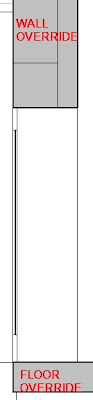
If there are view specific overrides on objects and you need them to go away, so the representation of the object(s) become default (again) then here you go:
I'll illustrate the Un-Overriding of the wall object...
 Select the object/Right Click/Override Graphics in View/By Category
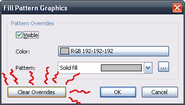
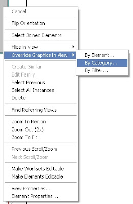 Click the appropriate button: In this case it's the Cut Pattern for said walls...
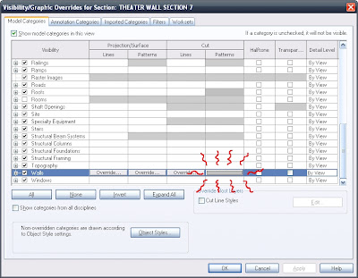 Next: Clear Overrides.
 After you "OK" yourself all the way out it will be back to default.
Have fun...
Nonetheless:
If there are view specific overrides on objects and you need them to go away, so the representation of the object(s) become default (again) then here you go:
I'll illustrate the Un-Overriding of the wall object...
 Select the object/Right Click/Override Graphics in View/By Category
 Click the appropriate button: In this case it's the Cut Pattern for said walls...
 Next: Clear Overrides.
 After you "OK" yourself all the way out it will be back to default.
Have fun...
Subscribe to:
Posts (Atom)